Prep
Body
Frt suspension
Cooling
Steering column
Horn
Heater A/C
Water lines
Brakes
Engine
Rear Suspension
Exhaust
Shifter
Seat belts
Body
Pedals
Electrical
Battery
Body seals
Interior
Final
Parts
Diagrams
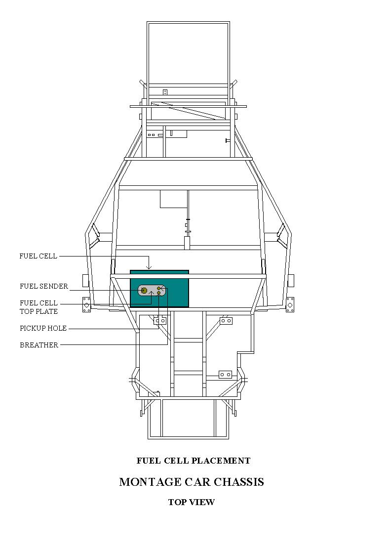
- Parts included with the Fuel Cell:
1. The fuel cell with interior foam packing.
2. A fuel cell shroud (sheet metal).
3. A filler cap and cell top plate.
4. Fuel sender unit with float arm.
5. Check valve breather (barrel type).
6. 90 degree bulkhead filling with a fuel draw tube.
7. Bolts for attaching top plate to fuel cell.
Fuel Cell Assembly:
The fuel cell has one end that is deeper than the other end. The deep end will be positioned closest to the driver’s side of the chassis. The shallow end will set over the water lines in the center of the chassis.
1. Pull all of the foam out of the fuel cell. Remember how it all comes out so you can replace it later.
2. The top plate will locate with the sender unit nearest the side of the fuel cell (not the center).
3. Mount the sending unit in the top plate keeping in mind that the float arm will swing its arc toward the center of the fuel cell.
4. Install the float arm in the slide lock adjuster on the sender unit. The float should be mounted horizontal to the fluid level in the fuel cell.
5. Set the top plate on the fuel cell in its proper position. Lift up on the plate high enough on the outside edge to see inside the cell. Move the float arm through its arc to check for clearance on the cell. Adjust the float arm so you have about 1 ˝ inches of clearance at its closest point of contact.
6. Once the proper arc is determined, trim the unused portion of the float arm about 1 ˝ " behind the slide lock adjuster.
7. Now determine how high and how low the float is traveling inside the fuel cell. Try to adjust to its lowest position possible by slightly bending float arm.
8. Install the check ball breather in the top plate (hole with the threads).
9. The other hole is for the fuel pick-up tube. Attach the 90 degree bulkhead itting to the top plate. Use the rubber o-ring supplied for sealing. Attach the aluminum draw tube to the fitting. Set the top plate back in the fuel cell and check for length on the draw tube. The draw tube should rest about 1" from the bottom of the fuel cell. Cut to length.
10. Put the foam back into the fuel cell. As you can see, there will have to be some foam cut out for clearance for the float to operate and for the draw tube to go to the bottom of the cell. When cutting the foam, try to engineer the cut for clearance for these parts and also leaving material to bridge the foam so it won’t collapse on the working parts.
Mark the foam with a felt tip marker and cut it using a sharp serrated steak knife. Cut in a sawing motion.
11. After the foam is all cut and you can see all the moving parts have clearance inside the fuel cell, it’s time to mount the top plate.
12. The top plate is mounted inside the fuel cell. The screws go through the fuel cell flange and thread into the top plate. Start all screws before tightening. After all screws have been started, squirt some silicone caulking between fuel cell flange and the top plate and tighten. This will seal the top plate.
Fuel Cell Shroud:
Install the fuel cell into the fuel cell shroud.
Position the fuel cell in the chassis under the roll bar cross-arm. The shallow end of the fuel cell will be in the center of the chassis. Locate the fuel cell as far to the left side of the chassis as possible without hitting the roll bar support tube. (approximately 1" clearance)
Drill (3) 5/16" holes on the bottom frame mount flange on the fuel cell shroud. Drill and tap threads into the chassis cross-member at the same locations for mounting. Drill 1 hole on each side of the fuel cell shroud, on the top side, mounting flanges. This will bolt to the body firewall later.