Prep
Body
Frt suspension
Cooling
Horn
Fuel Cell
Heater A/C
Water lines
Brakes
Engine
Rear Suspension
Exhaust
Shifter
Seat belts
Body
Pedals
Electrical
Battery
Body seals
Interior
Final
Parts
Diagrams
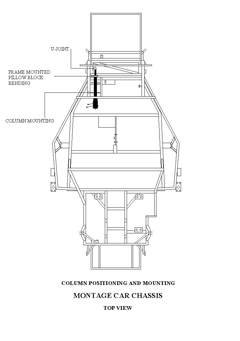
Steering Column Installation
The steering column with all the necessary modifications, along with u-joint coupling device, is available through Manta Cars.This unit makes for an easy bolt in application. All brackets are already installed on the chassis for this assembly.
- Installation:
1. Slide the female splined connector on to the steering shaft on the steering rack. There is a master spline on both pieces; make sure they are properly aligned before connection is made. Insert the bolt supplied for the connector and tighten.
2. Bolt the top end of the steering column to the mounts provided on the chassis. (Use ˝" 20 x 1 ˝ long bolts) Bolt up from the bottom side, use washers.
3. The steering column is supplied with a pillow block bearing with mounting bracket. This bracket is to locate off of the chassis cross member.
4. Drill holes and bolt into position. This will hold the steering column rigid and in the proper location.
Steering Column Modification:
1. Position the steering column in the chassis. Bolt it to the mounting brackets supplied on the chassis nearest the dash location.
2. Mark the steering column housing at the rear edge of the front cab cross member. Measure up the column 3 inches and mark again. (use masking tape to wrap around column for a straight edge all the way around)
3. Pull the steering column out of the chassis.
4. Put the steering column in a bench vise. Using a hacksaw, saw through the (outer) steering column housing at (the second line marked) all the way around the housing until they separate. Repeat this process on the inner housing until they separate.
5. Pull off the end of the housing.
6. Place the end of the housing (that you have cut off) in the bench vise and cut off the bushing end about 1 Ľ" back on the metal housing from the metal end. Keep the bushing portion and discard the remainder (use masking tape as before for marking).
Portions eliminated are:
A. Inner and outer housing between the first cut and the second cut.7. Now inspect column
B. Neutral safety switch
C. Gear selector shifting linkage.
A. Put the key in the ignition and make sure it operates in all positions. If it doesn’t, rotate the upper housing until the key works in all positions. Use masking tape and apply tape to the steering column upper housing and the lower housing and mark timing so you can be sure you retain this position (this is very important). B. At the end of the column that was cut you should space the inner and outer column housing equally by shimming.
1. You can use the proper size tubing to space them.
2. Use shim stock to space them
3. or tack weld for spacing
After spacing is positioned by any of these methods, tack weld into position.
C. Slide the bushing over the steering tube up tight against the outer column housing position into the stock location and tack weld into position.8. This completes the column modifications to this point.
D. Remove the plastic bushing (pull off spring clip, bushing willcome out) then weld the housing up all the way around. (removing the bushing will keep it from burning up when welding column)
E. After the column cools, replace the bushing.
9. Steering coupler (from the column to the steering rack is available from Manta Cars)
Parts needed:
A. One industrial type u-joint with a 5/8" counter bore at each end 1 1/8" outside diameter (can be found in most bearing supply houses)
B. The female splined coupler from the stock steering unit u-joint (Ford Pinto type)
It will be necessary to machine two shafts approximately 8 inches long. The shaft that connects to the coupler and runs to the u-joint will be 5/8" in diameter with a Ľ" thick flange at one end. The flange should measure about 1" in diameter.
The female coupler will be welded to the flanged end of the shaft. When welding the shaft to the coupler, attach the coupler to the splined steering shaft on the steering rack, and install the bolt in the coupler and tighten.
Align the machined shaft with the steering shaft in the rack and tack on 3 sides into position then weld all the way around.
The second shaft to be machined will be 5/8" diameter at one end and will measure (the inside diameter of the steering column tube) on the other end (usually the inside measurement is about ľ", but can vary from column to column). Install the steering column in the car.
Slide the spud shaft into the end of the column steering tube on the 5/8" end of the spud shaft. Install the u-joint. Install the steering rack on the chassis and measure both shafts where they intersect to accept the u-joint. The spud shaft will slide in and out of the steering column tube for adjustment.
The coupler shaft will have to be cut to proper length.
After the whole assembly is into place, mark all of the pieces in their respective positions, then remove from the chassis.
1. With the steering column out of the car, weld the spud shaft into position.
2. Weld the u-joint onto the spud shaft
3. Weld the steering coupler shaft to the u-joint.
This should complete the modifications necessary to install the steering column.